Question 1: The accompanying figure shows some electrical appliances connected in a circuit in a house. Answer the following questions.
A. By which method are the appliances connected?
Answer. The appliances are connected in parallel.
B. What must be the potential difference across individual appliances?
The potential difference (voltage) across each appliance is the same and equal to the voltage supplied by the main power source (e.g., 220V or 230V in many regions).
C. Will the current passing through each appliance be the same? Justify your answer.
Answer. No, the current passing through each appliance will not be the same. The current depends on the resistance of each appliance (using Ohm’s Law: I=V/RI=V/R). Since each appliance has a different resistance, the current drawn by each will differ.
D. Why are the domestic appliances connected in this way?
Domestic appliances are connected in parallel because:
- Each appliance gets the full voltage required for operation.
- If one appliance fails or is switched off, the others continue to work independently.
- It allows different appliances with different power ratings to operate simultaneously without affecting each other.
E. If the T.V. stops working, will the other appliances also stop working? Explain your answer.
No, the other appliances will not stop working. In a parallel circuit, each appliance has its own independent path to the power source. A fault in one appliance (like the TV) does not interrupt the flow of current to the others.
Question 2: The following figure shows the symbols for components used in the accompanying electrical circuit. Place them at proper places and complete the circuit. Which law can you prove with the help of the above circuit?
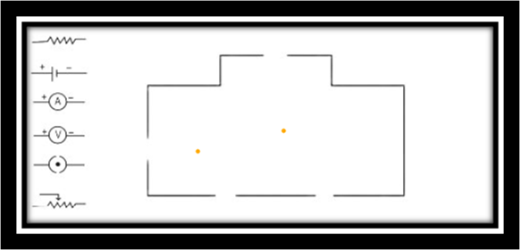
- The circuit likely includes components such as a battery, ammeter, voltmeter, resistors, and switches arranged to measure current and voltage across resistors.
- Circuit Completion: The battery is connected to a key/switch, and resistors are arranged in series or parallel with ammeters in series to measure current and voltmeters in parallel to measure voltage.
- Law Proven: This circuit can be used to prove Ohm’s Law, which states that the current through a conductor is directly proportional to the voltage across it, provided the temperature remains constant (V=IRV=IR).
Question 3: Umesh has two bulbs having resistances of 15 Ω and 30 Ω. He wants to connect them in a circuit, but if he connects them one at a time the filament gets burnt. Answer the following.
Connecting the bulbs in a series circuit has the following characteristics:
- Current: The electric current is the same through every bulb in the circuit.
- Resistance: The total resistance of the circuit is the sum of the individual resistances of the bulbs.
- Voltage: The total voltage supplied by the source is divided among the two bulbs. The voltage across each bulb will be proportional to its resistance.
- Circuit dependency: If one bulb burns out, the circuit becomes an open circuit, and the other bulb will also stop working.
C. Effective Resistance
The effective resistance of the circuit is the sum of the individual resistances.
Reffective=R1+R2
Given:
- R1=15Ω
- R2=30Ω
Reffective=15Ω+30Ω=45Ω
The effective resistance of the circuit will be 45 Ω.
Question 4: The following table shows current in Amperes and potential difference in Volts.
| V (Volts) | I (Amp) |
| 4 | 9 |
| 5 | 11.25 |
| 6 | 13.5 |
a. Find the average resistance.
To find the resistance for each pair of values, we use Ohm’s Law, R=IV.
- For V = 4 V and I = 9 A:
R1= 4 /9 = 0.44Ω
- For V = 5 V and I = 11.25 A:
R2= 5 / 11.25=0.44Ω
- For V = 6 V and I = 13.5 A:
R3= 6 /13.5 =0.44Ω
Since all three resistance values are approximately equal, the average resistance is also approximately 0.44 Ω.
b. What will be the nature of the graph between the current and potential difference? (Do not draw a graph.)
The graph between current (I) and potential difference (V) will be a straight line passing through the origin. This indicates a linear relationship where current is directly proportional to the potential difference.
c. Which law will the graph prove? Explain the law.
The graph proves Ohm’s Law.
Ohm’s Law states that the potential difference (v)across a conductor is directly proportional to the current (I) flowing through it, provided that all physical conditions, such as temperature, remain constant. The constant of proportionality is the resistance (R), which is a measure of how much a material opposes the flow of electric current. The law is mathematically expressed as V = I R
Question 5: Match the pairs
| ‘A’ Group | ‘B’Group |
| Free electrons | (a) V/R |
| Current | (b) Increase the Resistances in the circuit |
| 3. Resistivity | (c) Weakly Attached |
| 4. Resistances in series | (d)VA/LI |
| ‘A’ Group | ‘B’Group |
| Free electrons | (c) Weakly Attached |
| Current | (a)V/R |
| 3. Resistivity | (d) VA/LI |
| 4. Resistances in series | (b) Increases the resistance in the circuit |
Question 6: The resistance of a conductor of length x is r. If its area of cross-section is a, what is its resistivity? What is its unit?
The resistivity ρ of a material is given by the formula::
Ρ = r x a/ x
where:
- r = resistance of the conductor,
- a = area of cross-section,
- x = length of the conductor.
Unit of resistivity: The SI unit is ohm-meter (Ω⋅m).
Question 7: Resistances R1R1, R2R2, R3R3, and R4R4 are connected as shown in the figure. S1 and S2 are two keys. Discuss the current flowing in the circuit in the following cases.
Circuit Analysis:
- The circuit has a battery connected between points A and I.
- Resistors R3R3 and R4R4 are in series along the path A-G-I.
- Resistor R2R2 is connected between points B and E, with key S1S1 in series with it.
- Resistor R1R1 is connected between points C and D, with key S2S2 in series with it.
- The keys S1S1 and S2S2 control the flow of current through the branches containing R2R2 and R1R1, respectively.
a. Both S1S1 and S2S2 are closed.
- When both keys are closed, the branches containing R1R1 and R2R2 are connected in parallel with the series combination of R3R3 and R4R4.
- The total resistance of the circuit decreases due to the parallel paths.
- Current flows through all branches: R1R1, R2R2, and the series combination of R3R3 and R4R4.
- The total current drawn from the battery is the sum of the currents through the parallel branches.
b. Both S1S1 and S2S2 are open.
- When both keys are open, the branches containing R1R1 and R2R2 are disconnected.
- Only the series combination of R3R3 and R4R4 is connected to the battery.
- Current flows only through R3R3 and R4R4.
- The total resistance is R3+R4R3+R4, and the current is less than when both keys are closed.
c. S1S1 is closed but S2S2 is open.
- When S1S1 is closed, the branch containing R2R2 is connected.
- When S2S2 is open, the branch containing R1R1 is disconnected.
- The resistors R2R2 and the series combination of R3R3 and R4R4 are connected in parallel.
- Current flows through R2R2 and through R3R3 and R4R4.
- The total resistance is lower than when both keys are open but higher than when both are closed.
Summary of Current Flow:
- Both keys closed: Maximum current (lowest total resistance).
- Both keys open: Current only through R3R3 and R4R4 (higher resistance).
- S1 closed, S2 open: Current through R2R2, R3R3, and R4R4 (moderate resistance).
The exact current values depend on the resistances of R1R1, R2R2, R3R3, and R4R4, but the qualitative behavior is as described above.
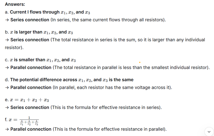
Question 8: Three resistances x1,x2x1,x2, and x3x3 are connected in a circuit in different ways. xx is the effective resistance. Match the properties to the connection type.
Question 9: Solve the following problems.
A. The resistance of a 1m long nichrome wire is 6 Ω. If we reduce the length of the wire to 70 cm, what will its resistance be?
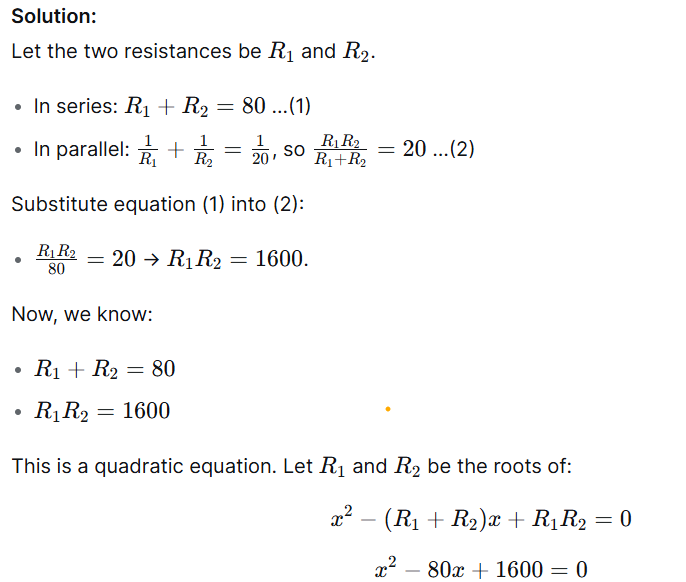
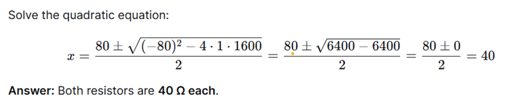
B. When two resistors are connected in series, their effective resistance is 80 Ω. When they are connected in parallel, their effective resistance is 20 Ω. What are the values of the two resistances?
C. If a charge of 420 C flows through a conducting wire in 5 minutes, what is the value of the current?